专业综合实验过程记录
实验1
加法器
一位全加器
对移位全加器而言,不同的写法有不同的综合结果。
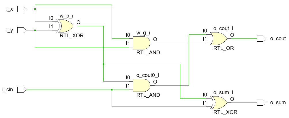
1
2
3
4
5
6
7
8
9
10
11
12
13
14
15
16
module adder( input i_x, input i_y, input i_cin, output o_sum, output o_cout ); wire w_p, w_g; assign w_p = i_x ^ i_y; assign w_g = i_x & i_y; assign o_sum = w_p ^ i_cin; assign o_cout = (w_p & i_cin) | w_g; endmodule
RTL分析:
image-20240509170552029
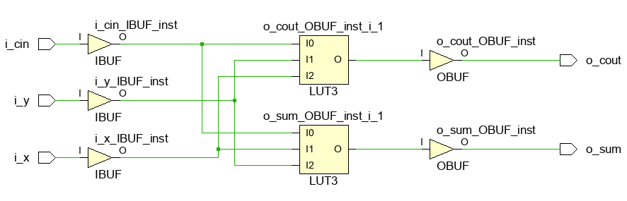
综合结果如下。可以看到FPGA内部通过查找表实现组合逻辑电路。
image-20240509170736387
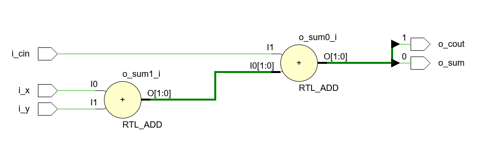
如果直接写加法:
1
2
3
4
5
6
7
8
9
10
module adder( input i_x, input i_y, input i_cin, output o_sum, output o_cout ); assign {o_cout, o_sum} = i_x + i_y + i_cin; endmodule
RTL分析:
image-20240509171015390
综合电路不变。vivado都会使用查找表(LUT)实现电路。
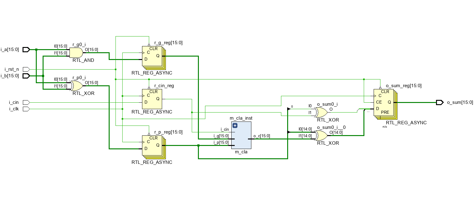
超前进位加法器
1 2 3 4 5 6 7 8 9 10 11 12 13 14 15 16 17 18 19 20 21 22 23 24 25 26 27 28 29 30 31 module m_adder( input i_x, input i_y, input i_cin, output o_sum, output o_p, output o_g ); wire w_p, w_g; assign o_p = w_p; assign o_g = w_g; assign w_p = i_x ^ i_y; assign w_g = i_x & i_y; assign o_sum = w_p ^ i_cin; assign o_cout = (w_p & i_cin) | w_g; endmodule
1 2 3 4 5 6 7 8 9 10 11 12 13 14 15 16 17 18 19 20 21 22 23 24 25 26 27 28 29 30 31 32 module m_cla # ( parameter NUM_BITS = 4 ) ( input i_cin, input [NUM_BITS - 1 :0 ] i_p, input [NUM_BITS - 1 :0 ] i_g, output [NUM_BITS - 1 :0 ] o_c ); wire [NUM_BITS - 1 :0 ] w_c; assign o_c = w_c; assign w_c[0 ] = (i_p[0 ] & i_cin) | i_g[0 ]; genvar i; generate for (i = 1 ; i < NUM_BITS; i = i + 1 ) begin assign w_c[i] = (i_p[i] & w_c[i - 1 ]) | i_g[i]; end endgenerate endmodule
1 2 3 4 5 6 7 8 9 10 11 12 13 14 15 16 17 18 19 20 21 22 23 24 25 26 27 28 29 30 31 32 33 34 35 36 37 38 39 40 41 42 43 44 45 46 47 48 49 50 51 52 53 54 55 56 57 58 59 module m_adder_fast_top # ( parameter NUM_BITS = 4 ) ( input [NUM_BITS - 1 :0 ] i_a, input [NUM_BITS - 1 :0 ] i_b, input i_cin, output [NUM_BITS - 1 :0 ] o_sum, output o_cout ); wire [NUM_BITS - 1 :0 ] w_p, w_g; wire [NUM_BITS - 1 :0 ] w_c; assign o_cout = w_c[NUM_BITS - 1 ]; genvar i; generate for (i = 0 ; i < NUM_BITS; i = i + 1 ) begin if (i == 0 ) m_adder adder_inst( .i_x (i_a[0 ] ), .i_y (i_b[0 ] ), .i_cin (i_cin ), .o_sum (o_sum[0 ] ), .o_p (w_p[0 ] ), .o_g (w_g[0 ] ) ); else m_adder adder_inst( .i_x (i_a[i] ), .i_y (i_b[i] ), .i_cin (w_c[i-1 ] ), .o_sum (o_sum[i] ), .o_p (w_p[i] ), .o_g (w_g[i] ) ); end endgenerate m_cla #( .NUM_BITS (NUM_BITS) )cla_inst( .i_cin (i_cin ), .i_p (w_p ), .i_g (w_g ), .o_c (w_c ) ); endmodule
tb文件
1 2 3 4 5 6 7 8 9 10 11 12 13 14 15 16 17 18 19 20 21 22 23 24 25 26 27 28 29 30 31 32 33 34 35 36 37 38 39 40 41 42 43 44 45 `timescale 1ns/1ns module m_adder_fast_top_tb; localparam NUM_BITS = 4 ; reg [NUM_BITS - 1 :0 ] i_a; reg [NUM_BITS - 1 :0 ] i_b; reg i_cin; wire [NUM_BITS - 1 :0 ] o_sum; wire o_cout; m_adder_fast_top # ( .NUM_BITS (NUM_BITS) ) m_adder_fast_top_inst ( .i_a (i_a), .i_b (i_b), .i_cin (i_cin), .o_sum (o_sum), .o_cout (o_cout) ); always begin #10 i_a = {$random } % 16 ; i_b = {$random } % 16 ; end initial begin i_a = 4'b0001 ; i_b = 4'b0010 ; i_cin = 1'b0 ; end endmodule
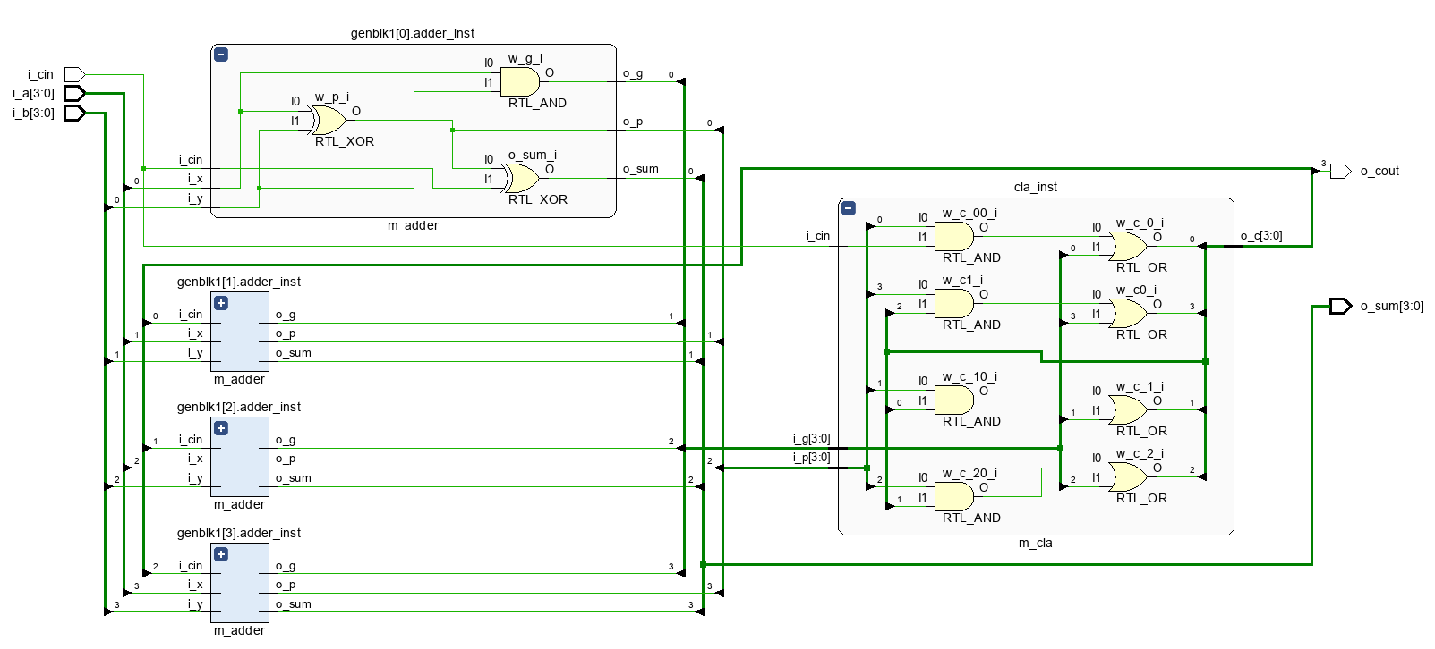
RTL电路
image-20240510000233924
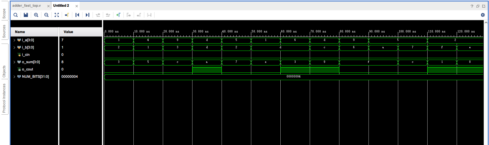
仿真结果
image-20240510000357125
乘法器
使用参数化设计的带符号数补码乘法器
1 2 3 4 5 6 7 8 9 10 11 12 13 14 15 16 17 18 19 20 21 22 23 24 25 26 27 28 29 30 31 32 33 34 35 36 37 38 39 40 41 42 43 44 45 46 47 48 49 module m_mul #( parameter NUM_BITS = 4 ) ( input [NUM_BITS - 1 :0 ] i_x, input [NUM_BITS - 1 :0 ] i_y, output [NUM_BITS * 2 - 1 :0 ] o_z ); wire [NUM_BITS - 1 :0 ] w_xy [NUM_BITS - 1 :0 ]; wire [NUM_BITS * 2 - 1 :0 ] w_temp [NUM_BITS - 1 :0 ]; reg [NUM_BITS * 2 - 1 :0 ] r_z; assign o_z = r_z; genvar i; generate for (i = 0 ; i < NUM_BITS; i = i + 1 ) begin assign w_xy[i] = i_x[i] ? i_y : {NUM_BITS{1'b0 }}; if (i == 0 ) assign w_temp[i] = {{(NUM_BITS-1 ){1'b0 }}, 1'b1 , ~w_xy[i][NUM_BITS-1 ], w_xy[i][NUM_BITS-2 :0 ]}; else if (i == NUM_BITS - 1 ) assign w_temp[i] = {{(NUM_BITS-1 ){1'b0 }}, 1'b1 , w_xy[i][NUM_BITS-1 ], ~w_xy[i][NUM_BITS-2 :0 ]}; else assign w_temp[i] = {{(NUM_BITS){1'b0 }}, ~w_xy[i][NUM_BITS-1 ], w_xy[i][NUM_BITS-2 :0 ]}; end endgenerate integer j; always @(*) begin r_z = 0 ; for (j = 0 ; j < NUM_BITS; j = j + 1 ) begin r_z = r_z + (w_temp[j] << j); end end endmodule
tb文件
1 2 3 4 5 6 7 8 9 10 11 12 13 14 15 16 17 18 19 20 21 22 23 24 25 26 27 28 29 30 31 32 33 34 35 36 37 38 39 40 41 module m_mul_tb; localparam NUM_BITS = 4 ; reg [NUM_BITS - 1 :0 ] i_x; reg [NUM_BITS - 1 :0 ] i_y; wire [NUM_BITS * 2 - 1 :0 ] o_z; m_mul # ( .NUM_BITS (NUM_BITS) ) m_mul_inst ( .i_x (i_x), .i_y (i_y), .o_z (o_z) ); always begin #10 i_x = $random % 8 ; i_y = $random % 8 ; end initial begin i_x = 4'b0001 ; i_y = 4'b0010 ; end endmodule
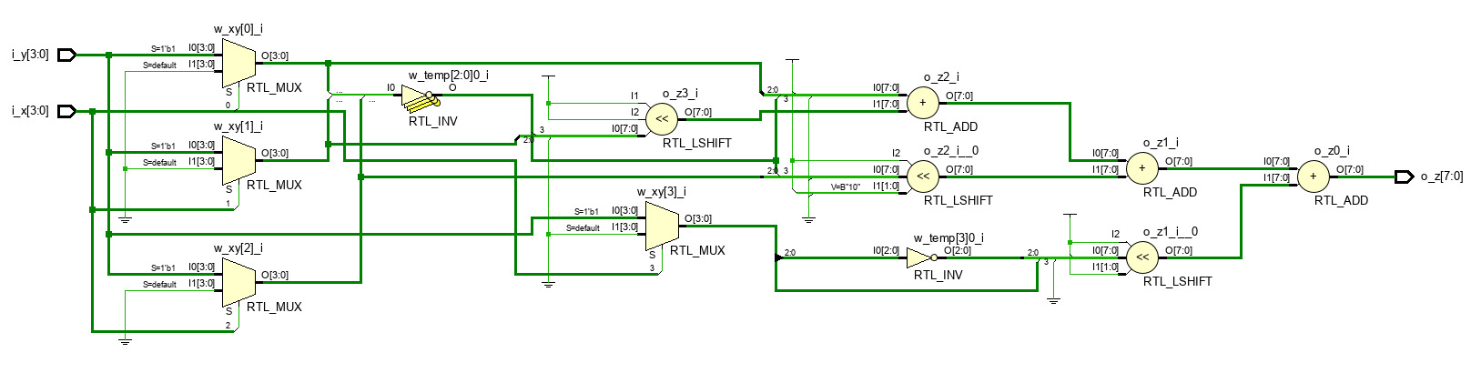
RTL电路
image-20240509225123110
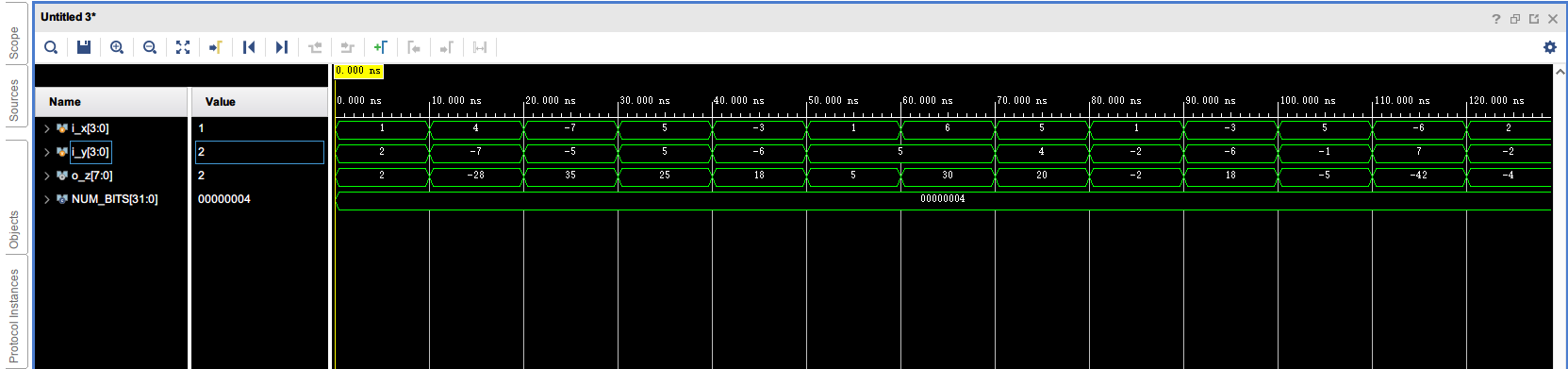
仿真结果
image-20240509225154373
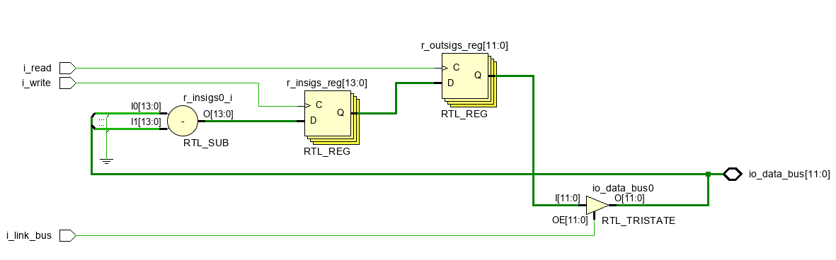
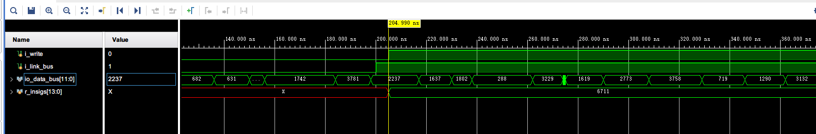
总线操作
1 2 3 4 5 6 7 8 9 10 11 12 13 14 15 16 17 18 19 20 21 22 23 24 25 26 27 28 29 30 31 32 33 34 35 36 37 38 39 40 41 42 43 44 45 46 47 `timescale 1ns/1ns module bus_operation_tb; reg i_write; reg i_link_bus; wire [11 :0 ] io_data_bus; bus_operation bus_operation_inst ( .i_write (i_write), .i_link_bus (i_link_bus), .io_data_bus (io_data_bus) ); initial begin i_write = 1'b0 ; i_link_bus = 1'b0 ; end always #200 i_link_bus = ~i_link_bus; always @(posedge i_link_bus) begin #5 i_write = 1'b1 ; end always @(negedge i_link_bus) begin #5 i_write = 1'b0 ; end always #({$random} % 30) force io_data_bus = {$random } % 4096 ; endmodule
image-20240515164948530
image-20240515165840189
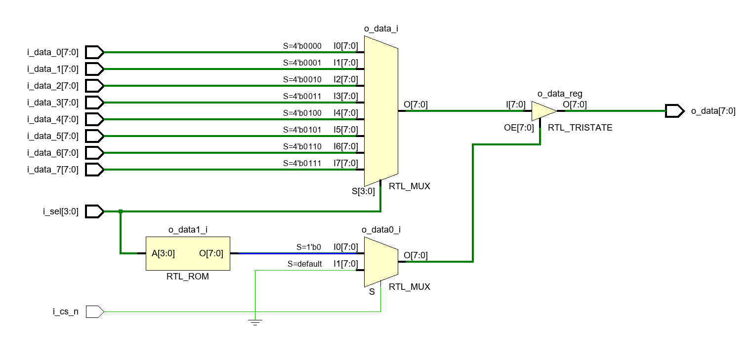
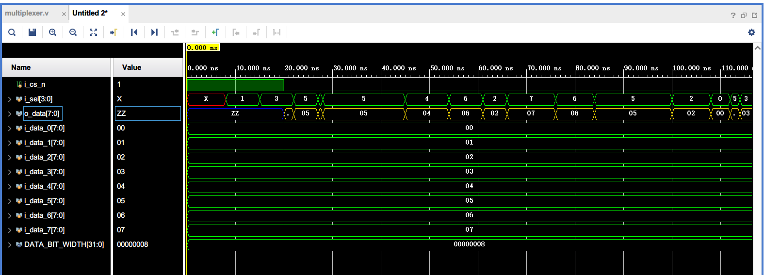
八选一数据选择器
1 2 3 4 5 6 7 8 9 10 11 12 13 14 15 16 17 18 19 20 21 22 23 24 25 26 27 28 29 30 31 32 33 34 35 36 37 38 39 40 41 42 43 44 45 module multiplexer_8 #( parameter DATA_BIT_WIDTH = 8 ) ( input i_cs_n, input [3 :0 ] i_sel, input [DATA_BIT_WIDTH-1 :0 ] i_data_0, input [DATA_BIT_WIDTH-1 :0 ] i_data_1, input [DATA_BIT_WIDTH-1 :0 ] i_data_2, input [DATA_BIT_WIDTH-1 :0 ] i_data_3, input [DATA_BIT_WIDTH-1 :0 ] i_data_4, input [DATA_BIT_WIDTH-1 :0 ] i_data_5, input [DATA_BIT_WIDTH-1 :0 ] i_data_6, input [DATA_BIT_WIDTH-1 :0 ] i_data_7, output reg [DATA_BIT_WIDTH-1 :0 ] o_data ); always @(*) begin if (!i_cs_n) case (i_sel) 3'b000 : o_data = i_data_0; 3'b001 : o_data = i_data_1; 3'b010 : o_data = i_data_2; 3'b011 : o_data = i_data_3; 3'b100 : o_data = i_data_4; 3'b101 : o_data = i_data_5; 3'b110 : o_data = i_data_6; 3'b111 : o_data = i_data_7; default : o_data = {DATA_BIT_WIDTH{1'bz }}; endcase else o_data = {DATA_BIT_WIDTH{1'bz }}; end endmodule
1 2 3 4 5 6 7 8 9 10 11 12 13 14 15 16 17 18 19 20 21 22 23 24 25 26 27 28 29 30 31 32 33 34 35 36 37 38 39 40 41 42 43 44 45 46 47 48 49 50 51 52 53 54 55 56 57 58 59 60 61 62 63 `timescale 1ns/1ns module multiplexer_8_tb; localparam DATA_BIT_WIDTH = 8 ; reg i_cs_n; reg [3 :0 ] i_sel; reg [DATA_BIT_WIDTH-1 :0 ] i_data_0; reg [DATA_BIT_WIDTH-1 :0 ] i_data_1; reg [DATA_BIT_WIDTH-1 :0 ] i_data_2; reg [DATA_BIT_WIDTH-1 :0 ] i_data_3; reg [DATA_BIT_WIDTH-1 :0 ] i_data_4; reg [DATA_BIT_WIDTH-1 :0 ] i_data_5; reg [DATA_BIT_WIDTH-1 :0 ] i_data_6; reg [DATA_BIT_WIDTH-1 :0 ] i_data_7; wire [DATA_BIT_WIDTH-1 :0 ] o_data; multiplexer_8 # ( .DATA_BIT_WIDTH (DATA_BIT_WIDTH) ) multiplexer_8_inst ( .i_cs_n (i_cs_n), .i_sel (i_sel), .i_data_0 (i_data_0), .i_data_1 (i_data_1), .i_data_2 (i_data_2), .i_data_3 (i_data_3), .i_data_4 (i_data_4), .i_data_5 (i_data_5), .i_data_6 (i_data_6), .i_data_7 (i_data_7), .o_data (o_data) ); initial begin i_cs_n = 1'b1 ; i_data_0 = 8'd0 ; i_data_1 = 8'd1 ; i_data_2 = 8'd2 ; i_data_3 = 8'd3 ; i_data_4 = 8'd4 ; i_data_5 = 8'd5 ; i_data_6 = 8'd6 ; i_data_7 = 8'd7 ; #20 i_cs_n = 1'b0 ; end always #({$random} % 10) i_sel = {$random } % 8 ; endmodule
image-20240510113224359
image-20240510112739108
实验2(流水线)
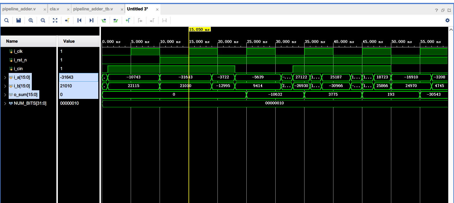
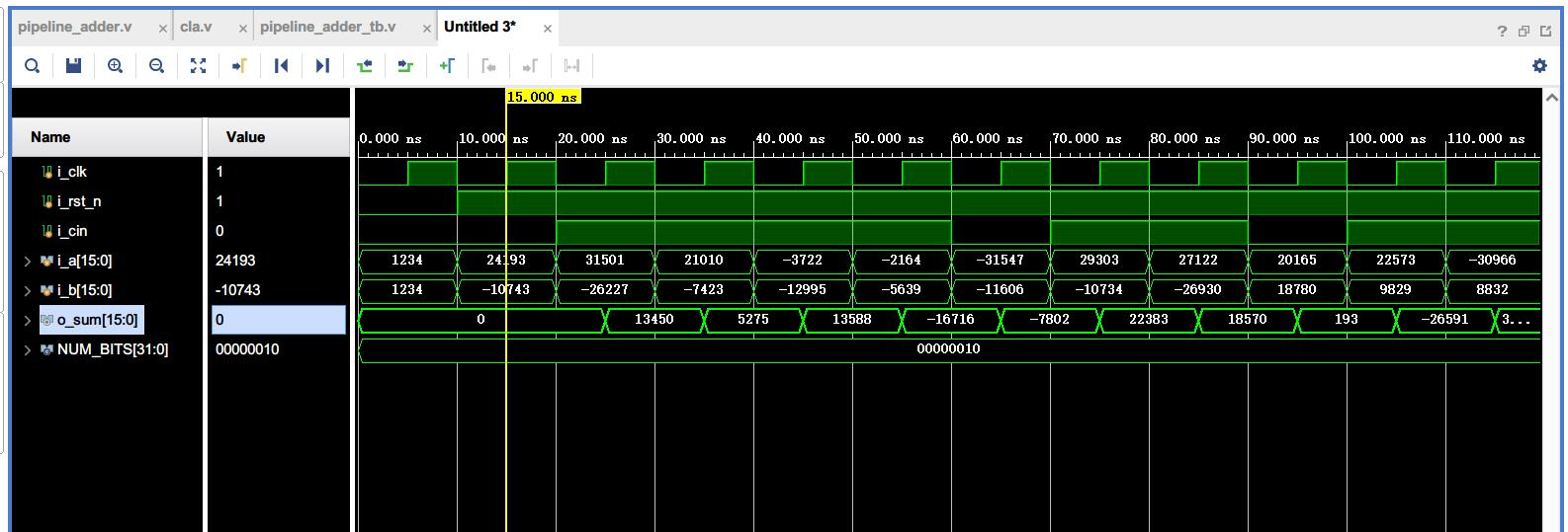
流水线加法器
image-20240511191350966
image-20240511185428856
image-20240511190028110
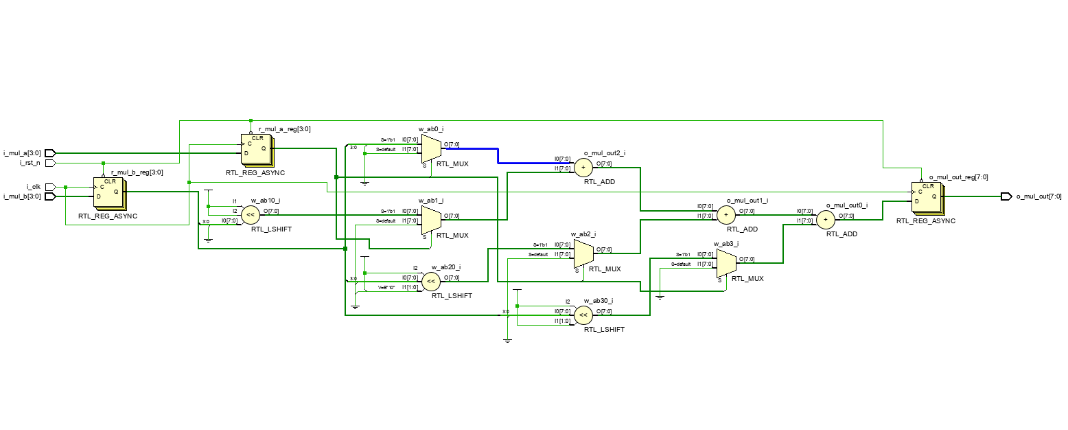
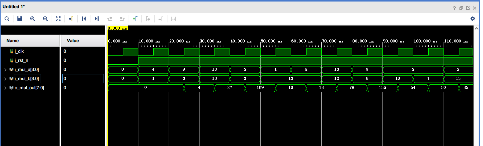
流水线乘法器
image-20240511191714349
image-20240511191817544
实验3(序列发生器)
case1:使用移位寄存器
image-20240516183519566
image-20240516183436275
case2:使用移位寄存器和组合反馈电路
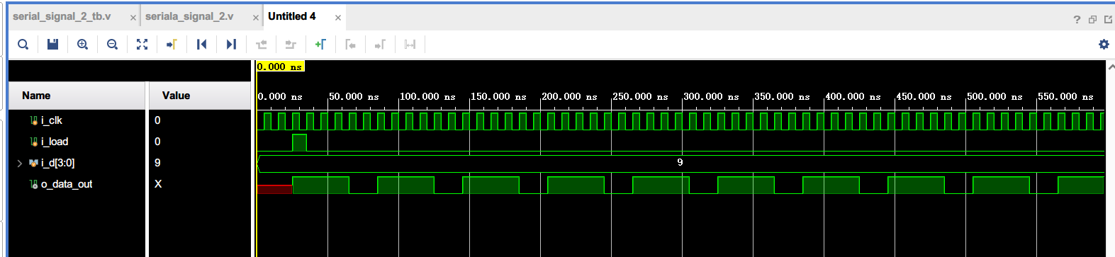
第一种设计的弊端在于数据输入端i_d的位数必须和要循环的序列长度相等。为了减少数据输入端的个数,才有了下面两种设计。
波形的序列是111001而不是100111,后续可以尝试排查一下问题。但是实际上问题不大,无论输入给了什么值输出都将回到这个回环,只是数据稳定所需要的时间不同,最长需要六个时钟周期。
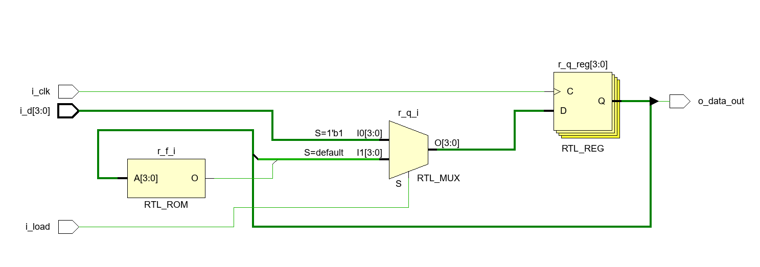
image-20240516184718780
image-20240516184743947
这里RTL模块综合出了一个RTL_ROM,很奇怪,预期的设计应该是由逻辑门组成的电路,而不是一块存储器,可能存在问题,可以将always语句块生成的组合逻辑电路改成化简后的与非门实现。
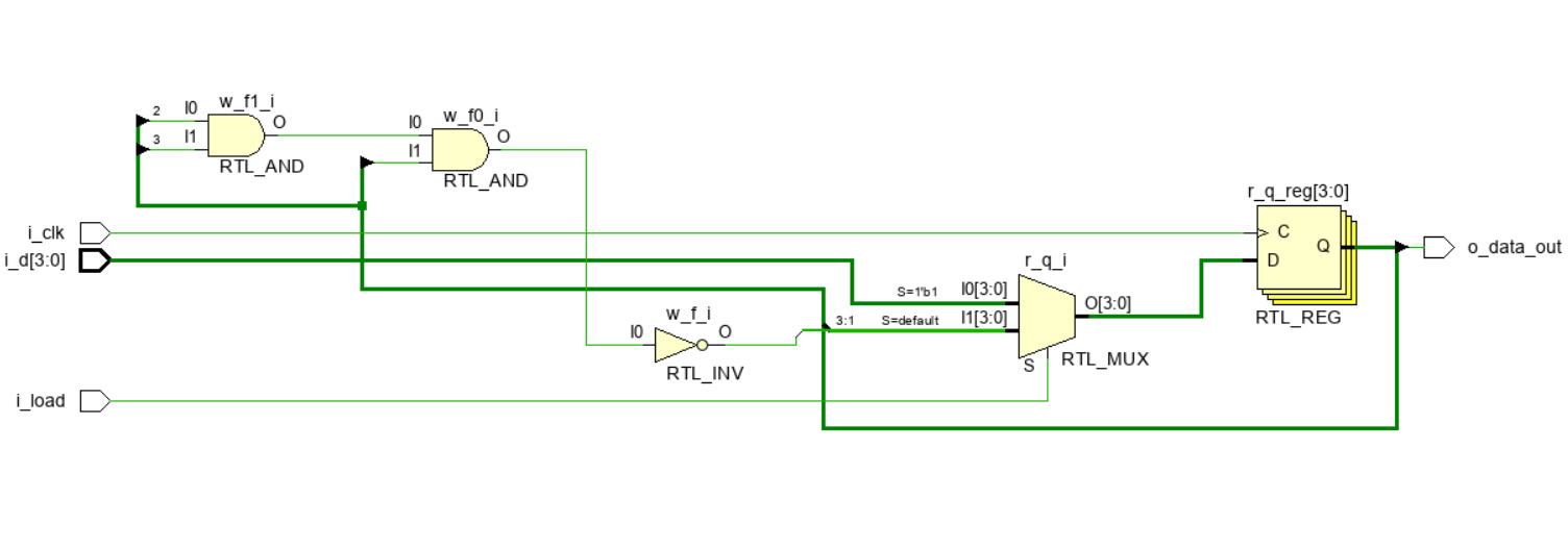
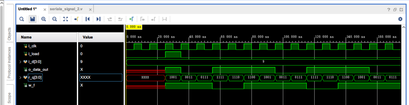
使用组合逻辑电路化简后实现:
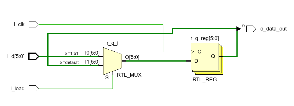
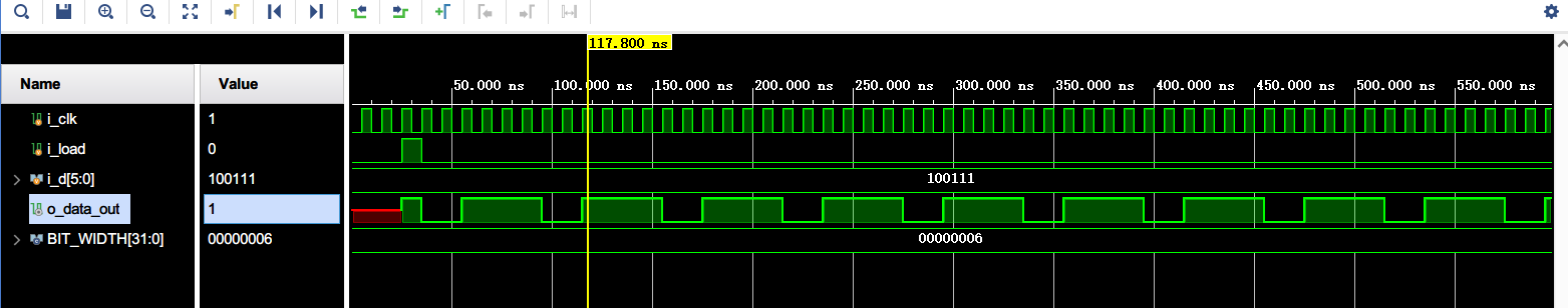
1 2 3 4 5 6 7 8 9 10 11 12 13 14 15 16 17 18 19 20 21 22 23 24 25 26 27 28 29 30 31 32 module serial_signal_2 ( input i_clk, input i_load, input [3 :0 ] i_d, output o_data_out ); wire w_f; reg [3 :0 ] r_q; assign o_data_out = r_q[3 ]; always @(posedge i_clk) begin if (i_load) r_q <= i_d; else r_q <= {r_q[2 :0 ], w_f}; end assign w_f = ~(r_q[1 ] & r_q[2 ] & r_q[3 ]); endmodule
image-20240522171445506
image-20240522171337256
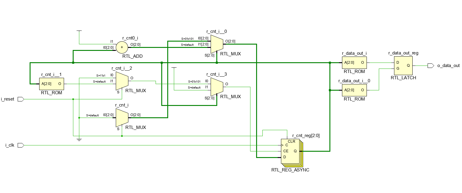
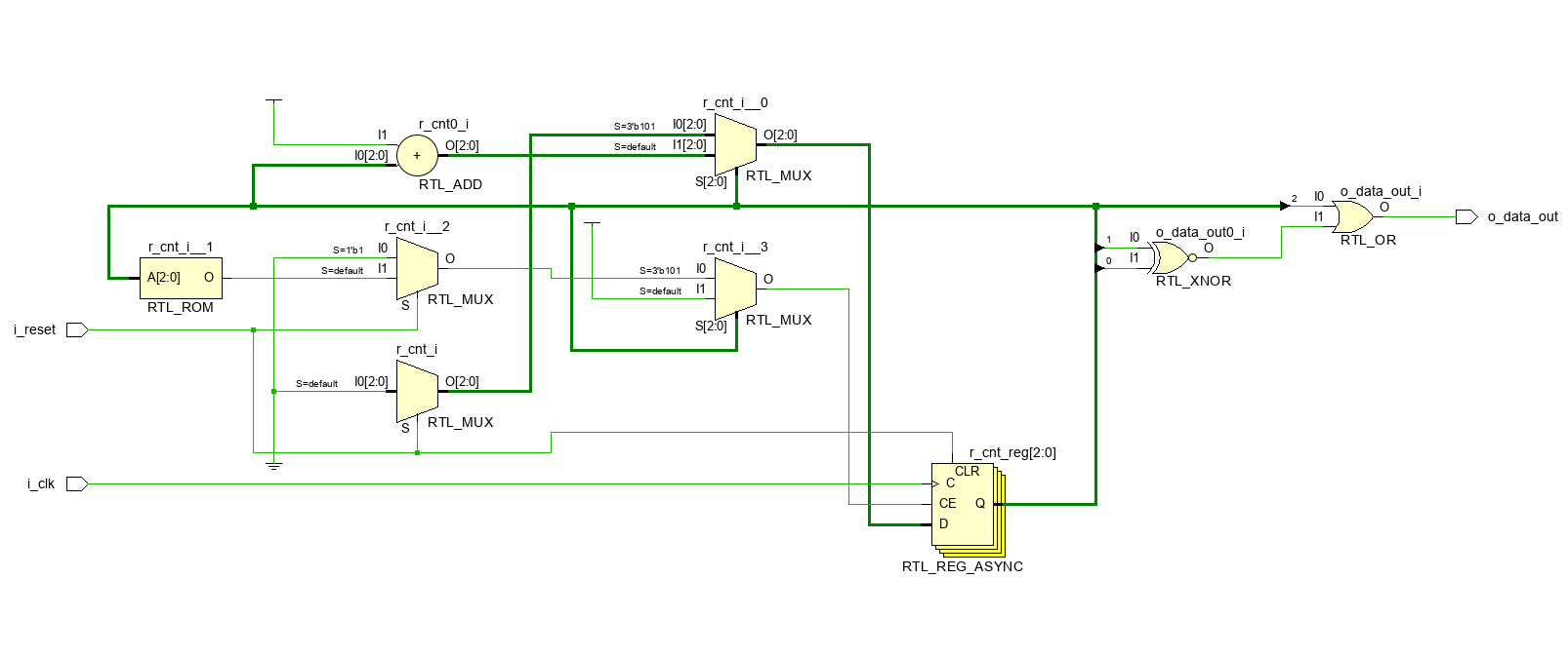
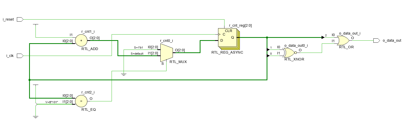
case3:使用计数器
第三种设计直接不需要数据输入端。
image-20240516185713716
不能这样写,否则综合器会认为有多个同步或者异步信号会执行复位操作,会报出一个critical warning。
1
2
3
4
5
6
always @(posedge i_clk or posedge i_reset) begin if (i_reset && r_cnt == 'd5 ) r_cnt <= 0 ; else r_cnt <= r_cnt + 1 ; end
要修改成:
1
2
3
4
5
6
7
8
always @(posedge i_clk or posedge i_reset) begin if (i_reset) r_cnt <= 0 ; else if (r_cnt == 'd5 ) r_cnt = 0 ; else r_cnt <= r_cnt + 1 ; end
非常蠢的错误,逻辑应该是或不是与。合起来写没有问题,实际应该写成:
1
2
3
4
5
6
always @(posedge i_clk or posedge i_reset) begin if (i_reset || r_cnt == 'd5 ) r_cnt <= 0 ; else r_cnt <= r_cnt + 1 ; end
image-20240516190117708
这里不仅生成了RTL_ROM,还生成了latch,后续可以尝试解决一下。
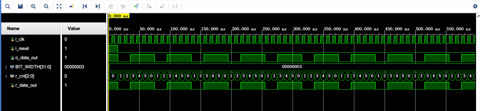
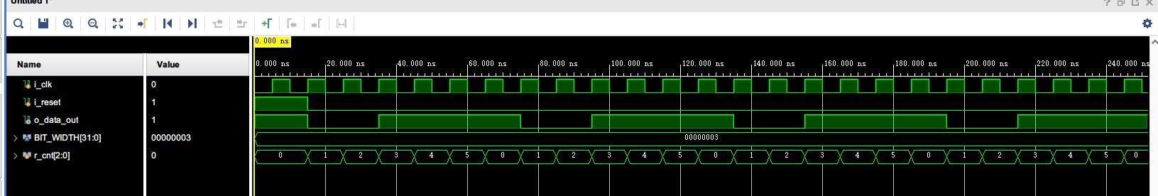
使用组合逻辑语句:
1 2 3 4 5 6 7 8 9 10 11 12 13 14 15 16 17 18 19 20 21 22 23 24 25 26 27 28 29 30 module serial_signal_3 #( parameter BIT_WIDTH = 3 ) ( input wire i_clk, input i_reset, output o_data_out ); reg [BIT_WIDTH-1 :0 ] r_cnt; always @(posedge i_clk or posedge i_reset) begin if (i_reset) r_cnt <= 0 ; else if (r_cnt == 'd5 ) r_cnt = 0 ; else r_cnt <= r_cnt + 1 ; end assign o_data_out = r_cnt[2 ] | (r_cnt[1 ] ~^ r_cnt[0 ]); endmodule
image-20240522174516467
image-20240522174532285
合并always语句块中的第一句和第二句:
image-20240522175229501
实验4
单端口RAM和双端口RAM的区别是地址总线的组数不同。单端口只有一个端口,同一时刻只能执行读操作或者写操作;双端口RAM有两套地址总线,可以形成两个独立的读写通道,读写的时钟也可以是异步的,即读写的时钟可以有两个。
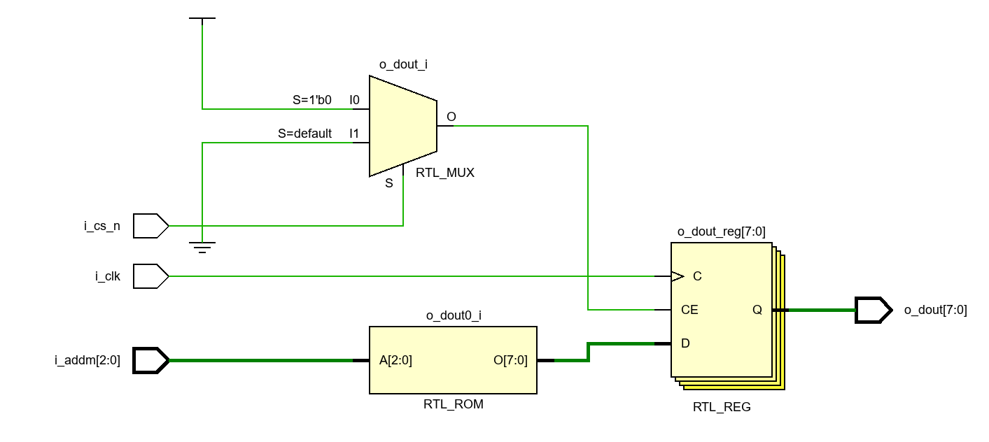
ROM
image-20240523164800574
image-20240523164605921
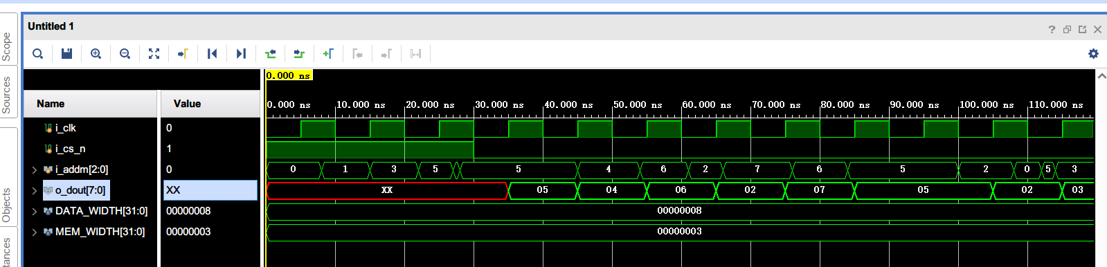
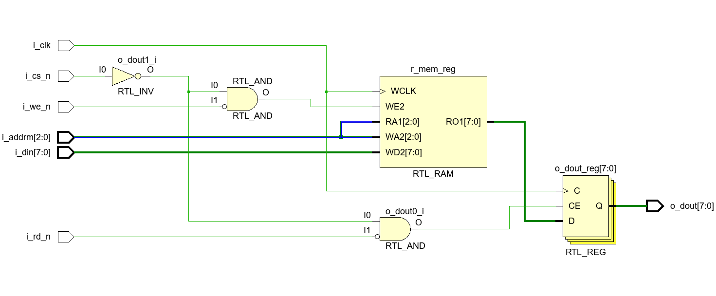
单端口RAM
image-20240523165500084
image-20240523165559752
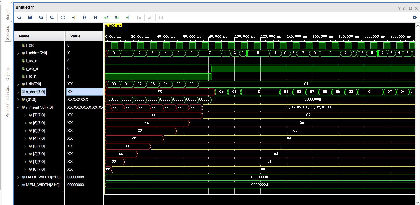
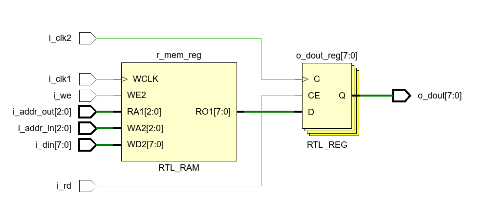
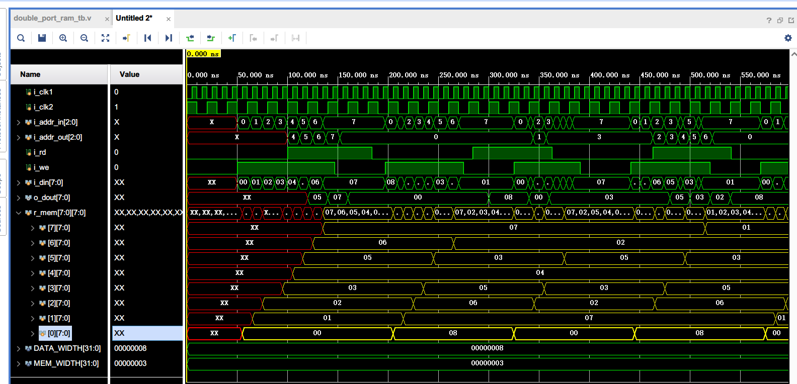
双端口RAM
image-20240523172226583
image-20240523172151471
实验5
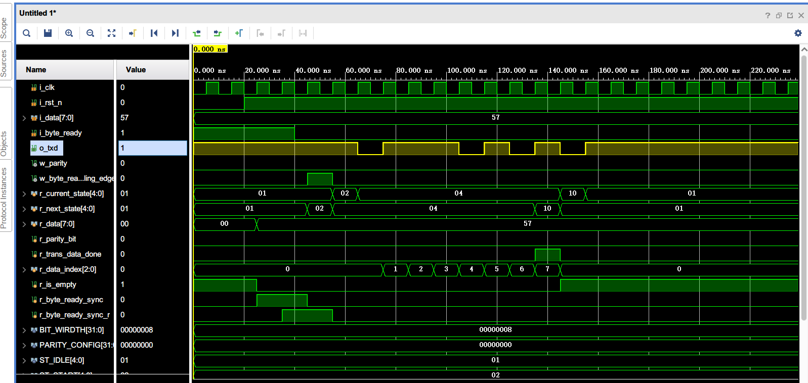
仅m_uart_tx模块:
image-20240530193225898
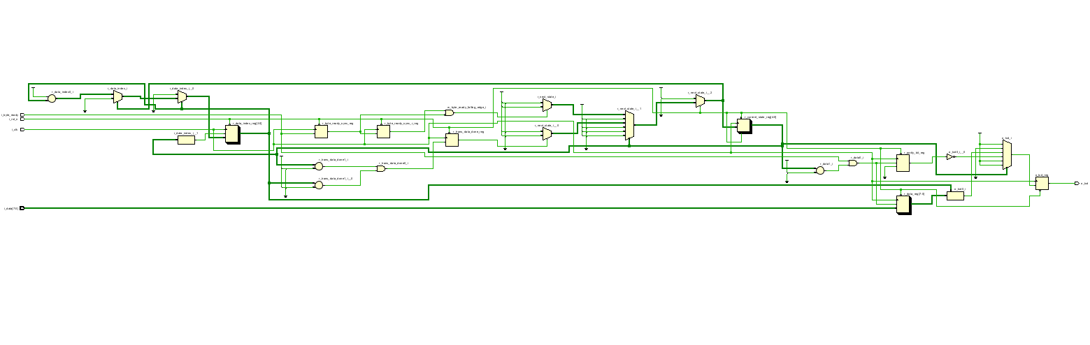
仿真跑通了,但是RTL分析报错 RTL分析
完全看不清
image-20240530192421704